PSW
PSW
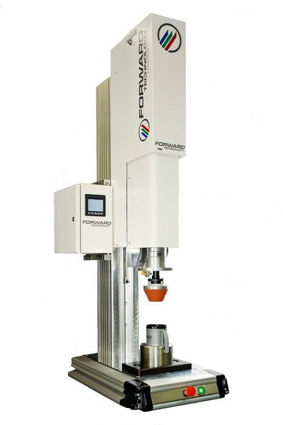
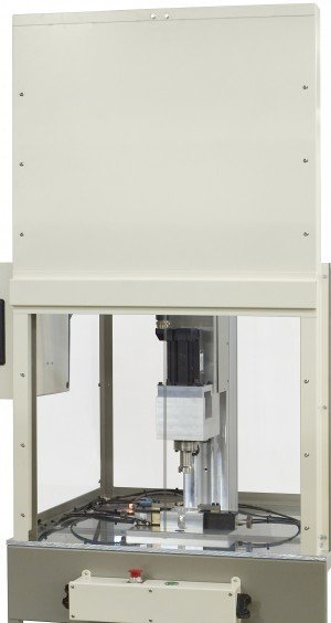
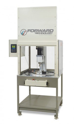
Inertial (Pneumatic Motor) Spin Welder
The PSW is a pneumatic motion controlled Inertial (Pneumatic Motor) Spin Welder designed for a wide variety of spin welding applications which do not require part to part orientation. This welder offers a simple approach to assembling parts with circular joints quickly and cost-effectively. Microprocessor control increases overall weld and production quality.
When compared to orientation (servo motor) models, inertial systems typically: Are available at a lower cost as simple pneumatic motors and basic control requirements allow lower equipment pricing. Generate higher operating speeds which often improve joint strength on lower durometer materials such as PE and PP. Allow all process energy (inertia) to be transferred to joint area as part to part contact causes rotation to cease, similar to a brake. Demand low power requirements as welding power is generated pneumatically as opposed to electrically.
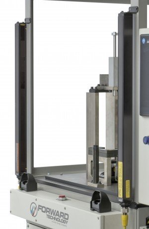
Light Screen Safety Protection (SW)
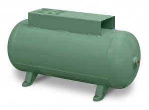
Compressed Air Reserve Tank
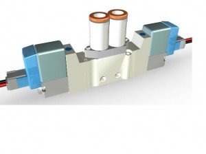
Fixture Clamp Valve
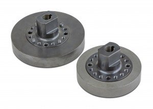
Driver Inertia Flywheels
Pneumatic Powered Safety Door
Welded Tubular Steel Support Frame w/ Leveling Feet (SW)
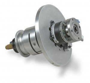
Electromagnetic Brake
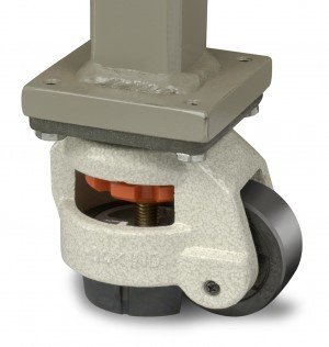
Heavy Duty Leveling Casters (Sm.)
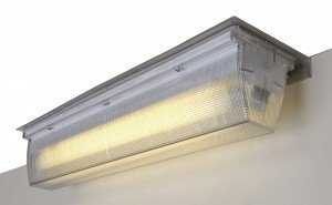
External Lighting (Sm)
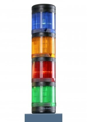
LED Four-Color Light Tower
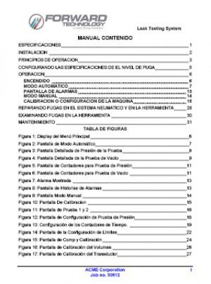
Bilingual Equipment Manual
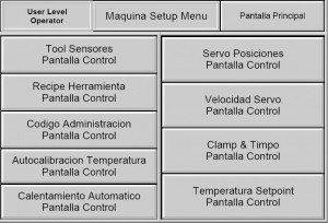
Bilingual User Interface Panel
Special Operating Voltages Transformer
- Operator loads part halves into holding fixture and driver.
- Operator initiates both cycle activation switches.
- Motor begins rotation and drivers speed (RPM) increases.
- When target RPM of driver is reached, the actuator moves driver & spinning part half toward stationary fixtured part half.
- Pneumatic motor is turned off at either user programmed height or automatically at 5mm prior to part halves contacting one another.
- Operator is permitted to release cycle activation switches after part to part contact is made.
- Spinning driver's rotation stops when all inertial energy is spent. Parts act as a brake against one another.
- If Optional Electromagnetic Brake is utilized, the spinning driver's rotation stops by actuation of brake when RPM speed decreases to a user programmed threshold or when reaching a user programmed height. This prevents breakage of solidifying material.
- Welded parts cool under pressure.
- Actuator retracts to home position.
- Operator removes welded part from fixture.