Spin Welders
Spin Welding is the preferred technique for thermoplastic parts with a circular axis joint which have high bond strength/hermetic requirements. During spin welding, one part is held stationary in a holding fixture while a second part is rotated against it under pressure at speeds up to 16,000 rpm. This resulting friction causes the joining surfaces to melt and fuse together, producing strong hermetic welds.
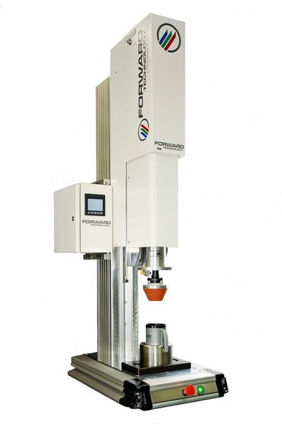
Forward Technology has been designing and building Spin Welders since 1993. We offer a multitude of models ranging in maximum speeds up to 16,000 RPM and are available in both servo-electric (orientation based) and pneumatic (inertial based) models for a wide array of applications.
Both pneumatic and servo z-axis control are options, Forward Engineering can assist you in determining which is best suited for your application.
About Orientation Spin Welding
Servo-Electric Drive Welding
About Inertial Spin Welding
Pneumatic Drive Spin Welding
Orientation vs. Inertial Spin
Comparison chart of welding factors
Designing For Spin Welding
Weld strength, materials & joints
Spin Weld Tooling
Advantages, standards & options
Spin Welding vs. Other Methods
Comparison chart of welding methods
We're Here to Help
Have A Question About A Product Or Service?


Spin Welding Process Advantages
Spin Welding is a frictional welding technique capable of producing strong, air-tight welds in thermoplastic parts with a circular-axis joint.
In this process, friction occurs by rotational motion controlled by either a servo electro-magnetic or pneumatic powered motor and motor control system which regulates the RPM (Revolutions Per Minute) and motion control of the system.
- Ability to weld parts with circular joint that are not easily welded by ultrasonics.
- Relatively fast cycle times when compared with other methods.
- Compatible with most thermoplastics.
- Ideal for welding of PP and PE materials.
- Ability to weld several dissimilar materials.
- No consumables, fumes or emissions.
- High strength, hermetic welds are typical.
- Heat confined to weld interface.
- Easily automated.
- Low cost, quick change tooling.
- Low maintenance.
- Low power consumption.
Designing For Spin Welding

The spin welding process produces a welded joint which, in many cases, yields a weld strength that is consistently equal to or stronger than any other area of the part.
As a result, the weld area can most often be exposed to the same strains and stresses as any other area of the part.
Spin Welding Joint Designs: A good spin welding joint should have a weld area equal to or greater than a typical wall section of the part. Joints should also provide sufficient part-to-part alignment.
Spin Weld Tooling
Driver: Custom-made tool used to "spin" the part and generate the weld.
Drivers commonly use raised or relieved surfaces to engage raised or relieved drive features on the spinning part half. Tapered silicone drivers can also be used on parts that do not have risen or relieved drive features.
Holding Fixture: The non-rotating part half must be held securely so that one part half does not rotate and remains in alignment with the spinning part half.
Part details such as protrusions and lugs/ribs on the outside of the part aid greatly in preventing rotation.