VHFIR-1015

VHFIR-1015
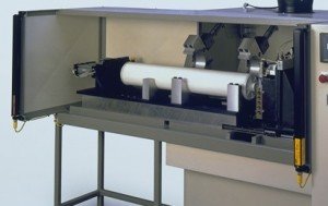
Vertical Hydraulic Filter Infrared Welder
The VHFIR-1015 is a vertical infrared platen orientation, hydraulic motion controlled infrared welding system specifically designed for welding filter assemblies up to 10" D x 15" x 69" L (254mm x 381mm x 1753mm). Customized variants of this model are available.
This system design is ideal for: Welding stackable filter cartridge modules together. Embedding filter media into plastic end caps (replacing potting operations). Welding of filtration housings. Welding termination fittings (ie: end-caps, twist-lock unions, O-ring fittings, etc...) to the ends of filter cartridge modules.
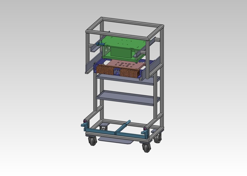
Infrared Tooling/Fixture Storage Cart w/ Casters
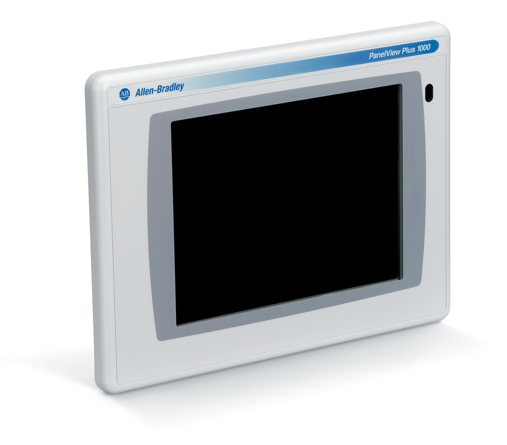
AB PanelView Plus 7 - 1000 Graphic Display Upgrade
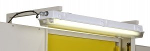
External Lighting (Lg.)
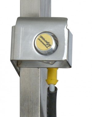
Quick Disconnect Tooling Sensors
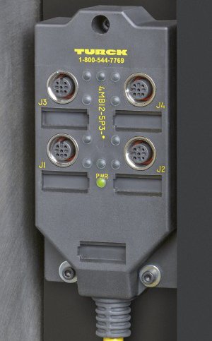
Quick Disconnect Outlets for Tooling Sensors
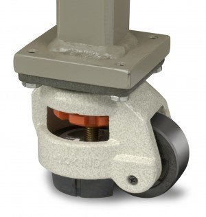
Heavy Duty Leveling Casters (Sm.)
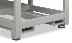
Fork Lift Tubes
Light Screen Safety Protection (HP)
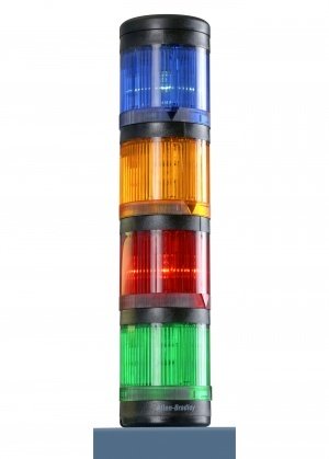
LED Four-Color Light Tower
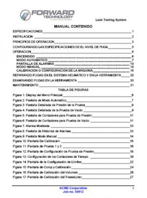
Bilingual Equipment Manual
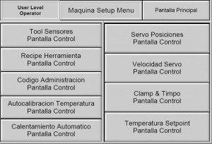
Bilingual User Interface Panel
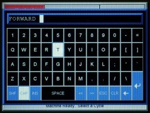
Individual User Passcode Log-In
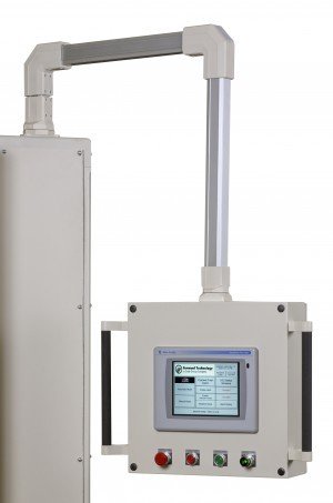
Pendant Arm Mounted User Interface
Special Operating Voltages Transformer
- Operator loads part halves into holding fixtures.
- Operator initiates cycle activation switch.
- Safety door closes.
- Part halves are automatically held with vacuum or mechanical clamps/grippers.
- Infrared platen advances between part halves.
- Holding fixtures close to make contact with precise mechanical hard-stops on the infrared platen which maintain spacing between the parts and the infrared platen without actual contact.
- Infrared platen energizes, heating joint areas of part halves.
- Infrared platen de-energizes and holding fixtures retract away from infrared platen.
- Infrared platen retracts.
- Holding fixtures apply part halves together, welding parts together.
- One holding fixture releases its clamping mechanism.
- Holding fixtures open, retaining welded part(s) in one fixture.
- Safety door opens.
- Operator unloads welded part(s).