About Infrared Welding
Infrared welding is a non-contact thermal welding technique capable of producing very strong, air-tight welds in thermoplastic parts.
Infrared radiation is most commonly felt in the form of the heat we feel from sunlight. As with any form of light, infrared radiation is electromagnetic radiation which is transmitted at very high power levels at the speed of light.
When using this energy in a tightly controlled manner, thermoplastic parts can be heated to molten temperatures very quickly and then joined together in a manner very closely resembling hot plate welding.
Glass encased infrared emitters are the assemblies which generate the infrared energy. Oscillating atoms within the heated conductors inside each emitter or “bulb” emit electromagnetic waves. Typically, the atoms within each conductor produce many different oscillation frequencies (wavelengths) but only some of which are harnessed to perform heating of plastic materials. The infrared wavelengths most often used for plastic welding are those of medium wavelength (approximately 2.0-2.5uM peak) and short wavelength (approximately 1.0-1.2uM peak).
Based on the properties of the plastic to be welded:
- most of the infrared radiation is absorbed within the material
- some of the infrared radiation is reflected off of the surface of the material
- some of the infrared radiation penetrates through the material.
Each infrared system is designed based on the specific wavelength range (medium or short) which will provide optimal absorption based on the material’s spectral analysis.
To heat the material, we utilize an infrared platen assembly consisting of multiple glass encased infrared emitters typically mounted side-side. We are able to target only the joint area of each part half. The targeting is made possible by infrared blocking masks which are used to prevent heating of non-joint areas.
Infrared Welding Process:

Step One
Part halves are placed into and securely gripped by precision holding fixtures which insure adequate support and accurate alignment of the part halves throughout the infrared welding process.
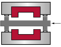
Step Two
To heat the part joint area, an infrared platen is placed between the part halves. The holding fixtures close to make contact with precise mechanical hard-stops on the infrared platen which maintain spacing between the parts and the infrared platen without actual contact.
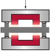
Step Three
Infrared energy is initiated, targeting the joint area of each part half only. As the material transitions to a molten state, the molten material remains in the joint area (no material displacement).
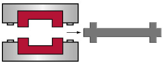
Step Four
After the joint area reaches molten temperature, the holding fixtures open and the infrared platen is withdrawn.
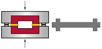
Step Five
The holding fixtures then close, forcing the two parts together until hard-stops on the holding fixtures come into contact with one another.

Step Six
When cooling is complete, the gripping mechanism in one of the holding fixtures releases the part, the holding fixtures open and the finished part may be removed.
Vertical vs. Horizontal Platen Systems:
| Vertical | Horizontal |
| Easy to manually load both part halves positively into the tooling, ensuring precise, repeatable alignment during welding. | More difficult to manually load both part halves positively as access to upper tool can be ergonomically challenging. |
| Not ideal when internal componentry is loose inside the part halves prior to welding. | Ideal system for part designs where internal components are loose inside the lower part half prior to welding. |
| No simple option for operator to load part halves outside the machine. | Allows option of manually loading part halves outside the machine (requires drawer load and automatic top-half part pick-up). |
| No special location features need be designed into the part halves or tooling for accurate alignment. | Requires special location features be designed into molded parts themselves or the tooling (increases tooling cost/complexity) when using automatic top-half parts pick-up. |
| Faster tool changeover than most horizontal machines offered today. | Slower tooling changeover typically. |
| More complex to automate (often requires robotic action). | Very easy to automate when optional drawer load and automatic part drop to conveyor belt is used. |
| Not ideal for automatic part drop (onto conveyor belt) after welding. | Allows easy automatic part drop onto conveyor belt after welding (when equipped with optional drawerload). |
| Twin motion (left and right) fixturing allows independent control of force/speed on each part half, both against heat platen and against each other. | Single motion (upper only) fixturing allows independent control of force/speed of upper part half only. |
- Infrared Intensity
- Melt Time (parts subjected to IR energy)
- Transition (aka: ‘Open’) Time between Melt and Weld/Seal Steps
- Weld/Seal Time (parts clamped together)
- Weld/Seal Depth (controlled by stops)
- Weld/Seal Force
The infrared absorption required to melt the part interface depends on the type, color and polymeric uniformity of the plastic being joined. Each thermoplastic has a characteristic melt time/absorption curve, and a weld can be produced at any point on the curve. Typically the highest possible intensity (without causing burning or unacceptable material degradation) using the shortest time is selected to minimize cycle times.
- Part dimensional stability
- Polymer uniformity
- Incoming line voltage
- Polymer color/translucency
- Mold release agents
- Dissimilar materials
- Infrared intensity
- Fillers
- Moisture
- Transition time between melt and weld steps