About Inertial (Pneumatic Drive) Spin Welding
Inertial Spin Welding is an economic yet highly effective technique of assembling thermoplastic components with a circular joint.
With Inertial Welding, energy (inertia) is stored in a spinning driver (and flywheel) and then lowered with applied pressure to the mating part in the fixture. In this process one part is held stationary in a fixture as the driver is rotated into it with pressure. The driver must be loaded with the mating part or must engage the part while rotating. With this process it is not possible to contact the part with the driver and apply pressure to the part before rotation begins to either compress or align the two mating parts before welding.
With Inertial spin welding applications it is important to have the appropriate conditions for spin welding success along with sturdy driving features to allow for proper engagement of the driver.
Inertial (Pneumatic) Spin Welding Advantages
- Lower Cost
- Higher speed (good for softer materials)
- All inertia is transferred to part (part/part contact stops rotation)
Inertial (Pneumatic) Spin Weld Process Steps:
| Spin-up: | At cycle start, air motor and spin driver begin rotation and build up to the user programmed RPM (rotation speed). |
| Motor-off: | When target RPM is reached, the supply to the air motor is shut off and head begins to decend. Spin Driver remains in rotation due to stored inertial. |
| Head-down: | Upper tooling moves downward until the part halves make contact. Parts act as a brake and rotation stops. |
| Hold/Cooling: | Pressure is maintained on the part after rotational welding motion has ceased. Allows thermoplastic material to solidify, ensuring the optimum bond of the two part halves. |
Inertial Spin Welding Rotational Speed:
The key requirement for spin weld applications is part symmetry around a common axis. This allows the parts to rotate around the spin weld joint. For proper welding, it is necessary for the weld to be rotated at a predetermined speed.
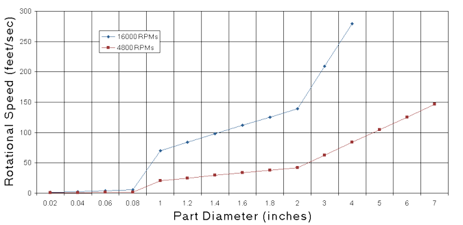
For Inertial Spin Welding, the range of the weld speed is expressed in the circumference speed, which is usually in feet/second. The appropriate inertial rotation can be derived from the following formula, linking the rotational speed with the part diameter:

An air motor can then be selected to fit the part requirement: 4,800 RPM or 16,000 RPM, Flywheels are available in various diameters to accommodate a wide range of materials and part diameters.
An Electromagnetic Brake Option is often incorporated for parts less than 1" in diameter for melt control purposes.